
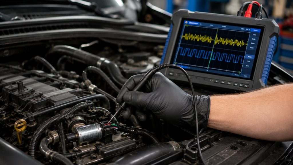
Basic code readers often miss crankshaft sensor dropouts because the signal can disappear before the ECM stores a fault code. Using high speed digital oscilloscopes, I monitor the crank and cam sensor waveforms live while the engine heats up and the wiring harness vibrates under load. The waveform shows whether the failure is inside the sensor, the wiring, the power supply, or the trigger signal before any parts are replaced.
Why Intermittent Sensor Failures Are Difficult to Diagnose
The ECM depends on crankshaft and camshaft position signals to maintain ignition timing, injector timing, and engine synchronization. The engine computer uses these signals to determine ignition timing, fuel injection timing, and engine speed.
When a sensor signal drops out, even briefly, the engine computer may lose synchronization and shut down fuel injection or ignition.
The failures I diagnose are often too brief for the ECM to log a code; the engine can lose synchronization before the fault monitor completes its test.
A vehicle may:
- Stall suddenly while driving
- Restart after cooling down
- Show no stored fault codes
- Operate normally during a short test drive
These failures often require monitoring the electrical signal while the problem is occurring.
Jacksonville Heat and Traffic Can Expose Electrical Weaknesses
Jacksonville’s summer heat and repeated idle cycles expose weak sensor circuits that may pass a cold inspection but fail after extended heat soaks in traffic.
Vehicles that spend extended periods idling in congested areas such as Blanding Boulevard experience repeated heat cycles that place additional stress on crankshaft and camshaft sensor systems. During prolonged summer idle conditions, heat-soaked sensor locations can reach temperatures high enough to expose marginal internal electronics and wiring weaknesses.
When these sensors heat up, I look for waveform changes before the signal disappears completely, small irregularities often appear before a full stall event.
These heat-related failures are often intermittent, which is why waveform testing under operating conditions can reveal problems that may not appear during a quick visual inspection or short test drive.
Understanding Crankshaft Position Sensor Types
The first step in diagnosing a crankshaft position sensor problem is identifying the sensor design because different sensors produce different waveform patterns.
Modern vehicles primarily use two types of engine speed sensors:
Inductive (Passive) Sensors
Inductive sensors generate their own AC voltage signal as a toothed reluctor wheel passes the sensor tip.
Normal operation produces a repeating sine-wave pattern that changes with engine speed.
Common failures include:
- Internal coil winding failure
- Increased resistance when hot
- Open circuits caused by broken internal wiring
A common pattern I see with inductive sensors is a clean waveform during a cold test followed by signal loss after the sensor reaches operating temperature.
Hall-Effect (Active) Sensors
Hall-effect sensors use electronic circuitry to create a digital signal.
The waveform switches between high and low voltage states as the reluctor wheel rotates.
Common failures include:
- Internal circuit degradation
- Heat-related electronic failure
- Intermittent signal dropouts
When the Hall-effect signal drops out, the ECM loses crank position reference and may immediately disable spark or injector operation.
Why Scan Tools May Miss Intermittent Sensor Failures
One of the biggest diagnostic challenges with engine stalls is the absence of fault codes.
A scan tool can only report what the ECM captures. If the crank signal disappears for milliseconds, the stall may happen before a diagnostic code is stored. If a crankshaft position signal disappears for a fraction of a second, the engine may stall before a permanent fault is stored.
This does not mean the system is working correctly.
A multimeter can measure voltage, resistance, and continuity, but it may average electrical changes over time and miss very brief signal interruptions.
The oscilloscope shows the electrical event itself, allowing me to see exactly when and how the signal changes.
With waveform analysis, I can separate sensor failure from wiring, power, and mechanical trigger problems by comparing the signal pattern.
- Signal dropouts
- Electrical noise
- Weak sensor output
- Wiring interruptions
- Irregular reluctor patterns
How Oscilloscope Testing Finds the Root Cause
When diagnosing a suspected crankshaft or camshaft sensor problem, I follow a structured testing process.
Connecting Directly to the Circuit
The oscilloscope is connected to the sensor signal wire, power supply, and ground circuit using proper back-probing methods.
This allows the signal to be measured without damaging sealed connectors or disturbing the circuit.
Monitoring the Live Waveform
A healthy sensor creates a repeatable pattern with consistent voltage transitions; the failure usually appears as a missing pulse, distortion, or sudden collapse.
During testing, the engine is monitored while reaching normal operating temperature.
If the sensor fails when hot, the waveform may show:
- Missing pulses
- Sudden signal collapse
- Irregular voltage transitions
- Complete signal loss
The captured waveform becomes the evidence that determines whether the repair is a sensor, wiring, or mechanical issue.
Checking the Reluctor Pattern
The waveform can also reveal mechanical problems.
A damaged reluctor wheel tooth, excessive debris, or an irregular trigger pattern can create a distorted waveform.
This lets me identify possible reluctor or timing-related problems before spending hours removing parts.
Why Testing Prevents Unnecessary Repairs
Replacing a crankshaft sensor may solve the problem, but only if the sensor is actually the cause.
Intermittent stalls can also come from:
- Wiring damage
- Poor electrical grounds
- Connector problems
- Power supply issues
- Reluctor wheel damage
- Control module faults
A proper diagnosis separates these possibilities before parts are replaced.
A no-code engine stall is not a guessing game. At Everything Automotive, we diagnose intermittent sensor failures by capturing the electrical signal while the problem occurs. Our oscilloscope testing helps determine whether the failure is coming from the sensor, wiring, power supply, or trigger system before unnecessary parts are installed. If your vehicle stalls after warming up or only fails under certain conditions, bring it to Everything Automotive in Jacksonville for a diagnosis based on evidence.
The objective is simple: identify the failure, confirm the cause, and perform the repair based on evidence.
Frequently Asked Questions
Can a standard code reader find an intermittent crankshaft sensor failure?
No. Basic code readers display stored diagnostic trouble codes but often cannot capture brief electrical signal interruptions that occur too quickly for the engine computer to record.
What are the signs of a failing crankshaft position sensor?
Common signs include intermittent engine stalling, hard starting, no-start conditions, a sudden drop in the tachometer signal, and rough engine operation.
Is an oscilloscope safe for modern vehicle computers?
Yes. Automotive oscilloscopes use high-impedance inputs designed to measure electrical signals without placing a significant load on sensitive vehicle circuits.
